An Operational Amplifier (Op-Amp) is a high-gain voltage amplifier with differential input and, usually, a single-ended output. It is one of the most versatile and widely used components in electronics, employed in applications such as signal conditioning, filtering, and mathematical operations like addition, subtraction, integration, and differentiation.
Structure of an Op-Amp:
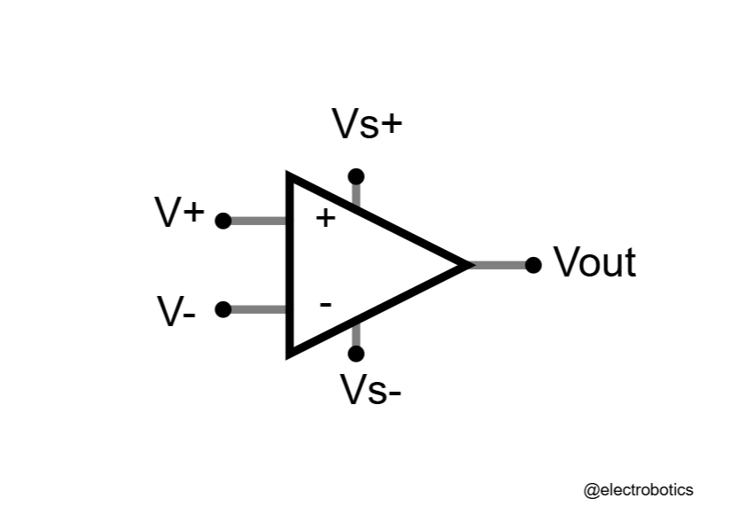
- Inputs:
- Inverting Input (-): Signal input where applying a voltage decreases the output.
- Non-Inverting Input (+): Signal input where applying a voltage increases the output.
- Output: The amplified version of the difference between the two inputs.
- Power Supply: Op-amps require an external power source (e.g., +Vcc and -Vee) to operate.
Working Principle of an Op-Amp:
An Op-Amp amplifies the difference between its two input voltages. The output is given by:
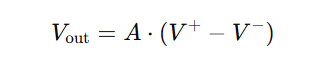
Where:
- Where, A is the open-loop gain (very high, typically 10^5 to 10^7).
- V+ represents the voltage at the non-inverting input, while V- represents the voltage at the inverting input.
Because the open-loop gain is very high, even a tiny difference between V+ and V− results in a significant output voltage.
Common Configurations of Op-Amps:
- Open-Loop Mode:
- In this mode, there is no feedback loop.
- So, the output either saturates at positive or negative supply rail depending on the input difference.
- Not commonly used in practical circuits.
- Closed-Loop Mode (with Feedback):
- Feedback stabilizes the gain and makes the circuit predictable.
- There are two types of feedback:
- Negative Feedback: Reduces the output a system and stabilizes the gain. It is the most common type.
- Positive Feedback: Enhances the output; used in oscillators and comparators.
Basic Applications:
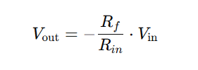
1. Inverting Amplifier:
- The input signal is applied to the inverting terminal through a resistor, and the non-inverting terminal is grounded.
- Output is inverted and proportional to the input.
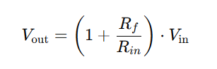
2. Non-Inverting Amplifier:
- Input is applied to the non-inverting terminal, and the inverting terminal is part of the feedback loop.
- Output is in a phase with input.
3. Buffer (Voltage Follower):
- A special case of the non-inverting amplifier with a gain of 1.
- Used to isolate circuits without loading. Isolating different stages of a circuit.
4. Summing Amplifier:
- Adds multiple input voltages and Combining multiple input signals.
5. Differentiator and Integrator Circuits:
- Perform mathematical differentiation and integration of signals.
6. Comparator:
- Compares two input voltages and outputs a high or low signal based on which is greater.
Key Characteristics of an Ideal Op-Amp:
- Infinite Open-loop Gain.
- Infinite Input Impedance (no current flows into the inputs).
- Zero Output Impedance (perfect voltage source).
- Infinite Bandwidth (works at all frequencies).
- Zero Offset Voltage (output is zero when inputs are equal).
In practice, real Op-Amps deviate slightly from these ideal characteristics but are designed to approximate them closely for most applications.