
Introduction:
In the area of robotics and electronics, controlling DC motors is a fundamental task. Whether it’s a simple robot, a remote-controlled car, or any other electromechanical project, having a reliable motor controller is crucial. In this guide, we’ll explore how to create a DC motor controller using the popular L298N DC motor driver with Arduino.
Components Required:
- Arduino Board: This is the brain of our project. Any Arduino board like Arduino Uno, Arduino Nano, or Arduino Mega will suffice.
- L298N DC Motor Driver: The L298N is a dual H-bridge motor driver integrated circuit that can control two DC motors simultaneously.
- DC Motor: You can use any DC motor suitable for your application. Ensure its voltage and current requirements are compatible with the L298N.
- Power Supply: Since the Arduino alone can’t power the motors, you’ll need a separate power supply. The voltage should match the motor’s voltage, and the current rating should be sufficient to drive the motors.
- Wires and Breadboard
1. Understanding the L298N DC Motor Driver:
- The L298N is a dual H-bridge motor driver integrated circuit that can control two DC motors simultaneously.
- Each H-bridge consists of four transistors. By controlling the state of these transistors, the motor’s direction and speed can be manipulated.
- The L298N also has built-in protection diodes, which prevent damage to the driver and other components from back electromotive force (EMF) generated by the motors.

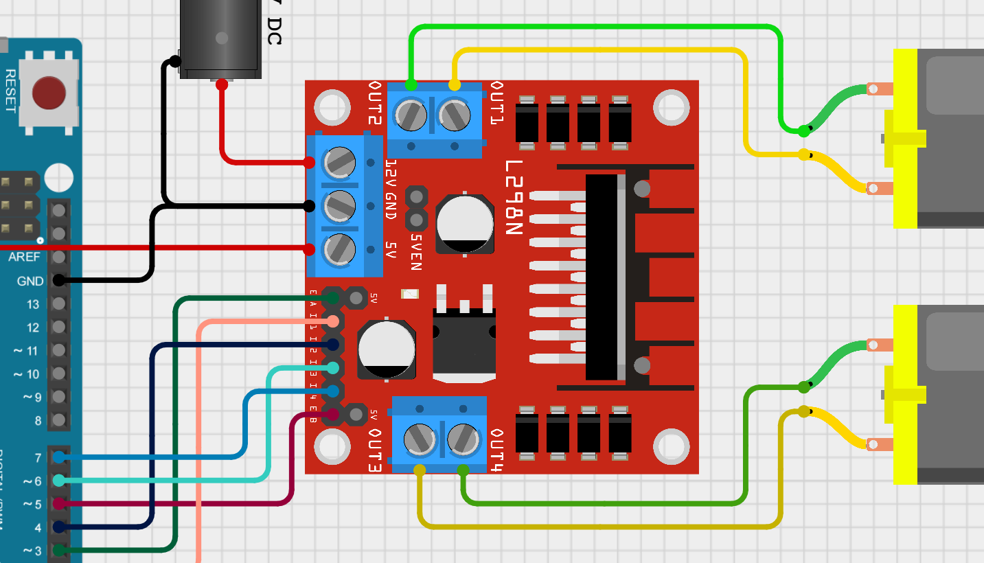
Circuit Diagram:

2. Circuit Overview:
- The circuit connects the Arduino, L298N motor driver, and DC motor(s) together.
- The L298N is powered separately from the Arduino, typically using an external power supply. This is because the Arduino’s onboard power source cannot provide sufficient current to drive motors.
3. Wiring Details:
- Motor Connections: The DC motor’s terminals are connected to the output terminals of the L298N motor driver. These terminals are labeled OUT1, OUT2 for Motor A, and OUT3, OUT4 for Motor B.
- Power Connections: The L298N requires both logic power (VCC) and motor power (VM). VCC powers the internal logic circuits of the driver, while VM powers the motors. Both VCC and VM should be within the specified voltage range of the L298N.
- Control Connections: The Arduino’s digital output pins are connected to the input pins of the L298N to control the direction of the motors. Additionally, the PWM-enabled pins of the Arduino are connected to the enable pins of the L298N to control the motor speed.

4. Working Principle:
- Direction Control: To control the direction of the motor, the Arduino sends signals to the input pins of the L298N. Depending on the combination of signals, the L298N configures the transistors in the H-bridges to drive the motor in either forward or reverse direction.
- Speed Control: The L298N utilizes PWM (Pulse Width Modulation) signals from the Arduino to control the speed of the motor. By adjusting the duty cycle of the PWM signal, the average voltage supplied to the motor is varied, thereby controlling its speed.
Circuit Explanation:
The L298N motor driver simplifies the task of controlling DC motors. It has two H-bridges, each capable of driving a single DC motor. The H-bridge allows us to control the direction and has PWM to control the speed of motor. The Arduino sends control signals to the L298N, which in turn drives the motors accordingly.
Arduino Code:
// Define motor control pins
int enableA = 3;
int enableB = 5;
int motorA1 = 2;
int motorA2 = 4;
int motorB1 = 7;
int motorB2 = 6;

void setup() {
  // Set motor control pins as outputs
  pinMode(enableA, OUTPUT);
  pinMode(enableB, OUTPUT);
  pinMode(motorA1, OUTPUT);
  pinMode(motorA2, OUTPUT);
  pinMode(motorB1, OUTPUT);
  pinMode(motorB2, OUTPUT);
}

void loop() {
  // Move motor A forward
  digitalWrite(motorA1, HIGH);
  digitalWrite(motorA2, LOW);
  // Set motor A speed
  analogWrite(enableA, 200);

  // Move motor B forward
  digitalWrite(motorB1, HIGH);
  digitalWrite(motorB2, LOW);
  // Set motor B speed
  analogWrite(enableB, 200);

  // Delay for 2 seconds
  delay(2000);

  // Stop both motors
  digitalWrite(motorA1, LOW);
  digitalWrite(motorA2, LOW);
  digitalWrite(motorB1, LOW);
  digitalWrite(motorB2, LOW);

  // Delay for 1 second
  delay(1000);
}
5. Arduino Code Breakdown:
- Pin Definitions: The code defines the pins used to control the motors and enable pins for PWM control.
- Setup Function: In the
setup()function, the Arduino sets the defined pins as outputs. - Loop Function: The
loop()function commands both motors to move forward at a speed of 200 (PWM value ranges from 0 to 255). It then stops the motors after a specified duration and repeats the process. - After 2 seconds, we stop both motors for 1 second before repeating the process.
6. Conclusion:
- The Arduino DC Motor Controller using the L298N DC Motor Driver provides a flexible and reliable way to control DC motors in various applications.
- Understanding the working principles of the L298N driver, the wiring connections, and the Arduino code allows for the effective implementation of motor control in robotics, automation, and other projects.
- Creating a DC motor controller using the L298N driver with Arduino is a fundamental step towards building various robotics and automation projects.