Introduction:
In the world of DIY electronics, Arduino has revolutionized the way enthusiasts and professionals alike approach projects. One of the fundamental aspects of many Arduino projects is interfacing with displays, and one popular choice is the 16×2 LCD (Liquid Crystal Display). In this guide, we’ll explore how to interface a 16×2 LCD with an Arduino board, providing a detailed project, circuit connections, Arduino code, and step-by-step instructions.
Understanding the 16×2 LCD Display: Working Principles and Display
LCD (Liquid Crystal Display) technology is widely used in various electronic devices, from digital watches to sophisticated instrumentation panels. The 16×2 LCD display, in particular, is a common choice for Arduino projects due to its simplicity and versatility.
Working Principles: The 16×2 LCD consists of two main components: liquid crystal material and a polarized glass substrate. The liquid crystal material is sandwiched between two glass plates, and each plate is coated with transparent electrodes. These electrodes allow voltage to be applied, causing the liquid crystal molecules to align in a particular orientation.
The 16×2 designation refers to the display’s dimensions: it has 16 columns and 2 rows, allowing for a total of 32 characters to be displayed. Each character position consists of a grid of pixels, typically 5×8 or 5×10 pixels per character.
Display Operation: When a voltage is applied to the electrodes, the liquid crystal molecules twist, changing their orientation and affecting the polarization of light passing through them. By controlling the voltage applied to each pixel, the display can selectively block or allow light to pass through, creating characters or graphics.
The display is controlled by an external driver, which communicates with the microcontroller (such as an Arduino) using parallel or serial communication protocols. The microcontroller sends commands and data to the display driver to control what is displayed on the screen.
Internal Structure: Internally, the 16×2 LCD consists of a controller chip, such as the HD44780, which handles the display’s operation and communication with the external driver. The controller chip interprets commands and data received from the microcontroller and generates signals to control the display’s pixels.
Display Features: The 16×2 LCD display typically includes several features, including:
- Character Set: The display supports a predefined character set, typically ASCII or a custom character set.
- Cursor Control: The display can show a blinking cursor to indicate the current position for writing data.
- Clearing Display: The display can be cleared to erase all displayed characters.
- Custom Characters: Some displays allow the creation of custom characters, enabling the display of icons or special symbols.
- Backlight: Many displays include a built-in LED backlight for improved visibility in low-light conditions.
Project Overview:
The project involves connecting a 16×2 LCD to an Arduino board and displaying text messages on the LCD screen. This setup can be used for various purposes, such as displaying sensor data, messages, or even creating simple user interfaces.
Components Required:
- Arduino Board (e.g., Arduino Uno)
- 16×2 LCD Display
- Potentiometer (for contrast adjustment)
- Jumper Wires
- Breadboard (optional)
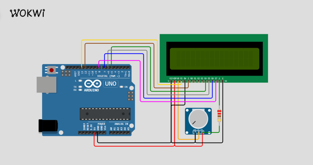
Circuit Connections:
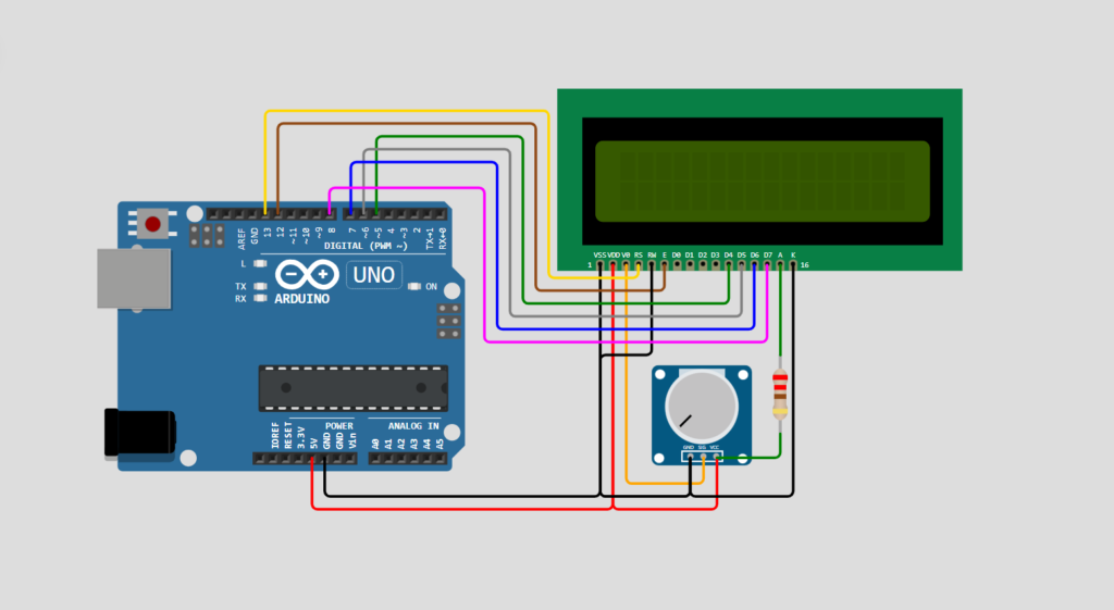
- Connect the VSS pin of the LCD to GND on the Arduino.
- Connect the VDD pin of the LCD to 5V on the Arduino.
- Connect the V0 pin of the LCD to the center pin of the potentiometer.
- Connect one end of the potentiometer to 5V on the Arduino and the other end to GND.
- RS pin of the LCD to digital pin 12 of Arduino.
- And RW pin of the LCD to GND.
- Connect E pin of the LCD to digital pin 11 of Arduino.
- Connect the D4-D7 pins of the LCD respectively to digital pins D5-D8 on the Arduino.
Arduino Code:
//simple code to print "hello world" on display

#include <LiquidCrystal.h>

LiquidCrystal lcd(12, 11, 5, 6, 7, 8);

void setup() {
  lcd.begin(16, 2);
}

void loop() {
  lcd.clear();
  lcd.setCursor(0, 0);
  lcd.print("Hello, Arduino!");
  delay(1000);
}
Steps to Connect:
- Connect the Arduino board to your computer using a USB cable or an external power supply.
- Build the circuit according to the provided connections.
- Open the Arduino IDE on your computer.
- Copy and paste the provided Arduino code into the IDE.
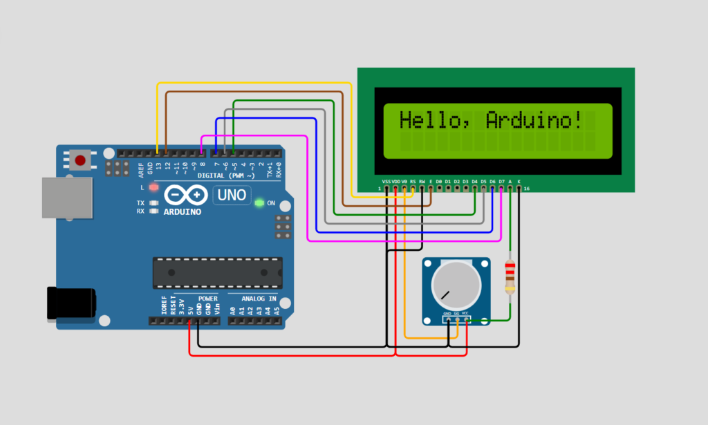
- Verify and upload the code to the Arduino board.
- Once uploaded, you should see the text “Hello, Arduino!” displayed on the LCD screen.
Applications and Usage:
- Sensor Readouts: Display real-time data from sensors such as temperature, humidity, light, etc.
- System Monitoring: Show status messages or alerts from a connected system or device.
- User Interfaces: Create simple interfaces for user interaction in projects such as alarms, timers, or menu systems.
- Educational Purposes: Learn about microcontroller programming, interfacing, and display technologies.
- Embedded Systems: Used as a user interface for embedded systems and microcontroller-based projects.
- Instrumentation: Displaying data and status information in instruments and control panels.
- DIY Electronics: Integrating with Arduino and other development platforms for educational and hobbyist projects.
- Consumer Electronics: Found in devices such as digital clocks, calculators, and small appliances.
Conclusion:
In this guide, we’ve learned how to interface a 16×2 LCD with an Arduino board, including circuit connections, Arduino code, and step-by-step instructions. This project opens up a world of possibilities for creating interactive and informative Arduino-based projects. With a solid understanding of these fundamentals, you can now embark on your journey of creating innovative electronics projects.
I agree with your points, excellent post.