
Efficient Power Conversion: Building a Full Wave Bridge Rectifier Circuit
Introduction:
A bridge rectifier circuit is a vital component in electronics, essential for converting alternating current (AC) to direct current (DC). It rectifies both the positive and negative half-cycles of an AC waveform, resulting in a continuous unidirectional flow of current. In this guide, we’ll walk you through the process of building a bridge rectifier circuit and explain its working principle.
In this project, we delve into the realm of power electronics by constructing a bridge rectifier circuit. This circuit serves a fundamental role in converting alternating current (AC) to direct current (DC) with improved efficiency and reduced ripple.
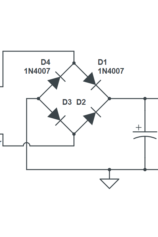
Using four diodes arranged in a bridge configuration, we harness the alternating voltage from the transformer and rectify it into a pulsating DC output. Each diode conducts during opposite half-cycles of the input AC waveform, ensuring continuous flow of current through the load resistor.
Furthermore, we have the option to incorporate a smoothing capacitor across the output terminals to further reduce ripple and provide a cleaner DC output voltage.
Sure! The formula to calculate the output voltage of a Bridge Rectifier Circuit is:
VDC=2×Vrms−2×Vd
Where:
- VDC = Output DC voltage
- Vrms = RMS (Root Mean Square) value of the input AC voltage
- Vd = Forward voltage drop across each diode
The factor of 2 in the formula accounts for the fact that the bridge rectifier utilizes both the positive and negative halves of the input AC waveform. The term 2×Vd represents the voltage drop across two diodes in series during each half-cycle of the input waveform.
Keep in mind that this formula assumes ideal conditions and may not account for factors such as transformer losses or diode non-idealities. Actual output voltage may vary slightly from the calculated value.
Components Needed:
- Transformer:
- Input voltage: 120V AC
- Output voltage: 12V AC
- Four diodes (silicon diodes are commonly used):
- Type: Silicon diodes (1N400X series)
- Maximum voltage: 50V to 1000V
- Maximum current: 1A to 3A
- Load resistor:
- Resistance: 100Ω to 1kΩ
- Power rating: 0.25W to 1W
- Smoothing capacitor (optional):
- Capacitance: 100µF to 1000µF
- Voltage rating: Equal to or greater than the maximum output voltage (e.g., 25V, 50V)
- These values are just examples and can be adjusted based on the specific requirements of your project, such as input voltage, desired output voltage, and load current. Be sure to choose components that are suitable for your application and within their rated specifications.
Step-by-Step Guide:
1. Transformer Connection:
- Begin by connecting the transformer’s secondary winding to the ground reference.
- Connect one end of each secondary winding to the input terminals of the bridge rectifier circuit.

2. Diode Configuration:
- Place four diodes in a bridge configuration, ensuring each diode’s anode connects to one end of the secondary winding, and each cathode connects to the other end.
- The arrangement should form a bridge-like structure, with diodes connected across the secondary winding in both polarities.
3. Load Resistor Connection:
- Connect the load resistor across the output terminals of the bridge rectifier circuit.
- This resistor represents the device or circuit that requires the rectified DC voltage.

4. Smoothing Capacitor (Optional):
- To reduce ripple in the output voltage, connect a capacitor across the output terminals of the bridge rectifier in parallel with the load resistor.
- This capacitor assists in smoothing out the rectified waveform, resulting in a more stable DC output.
Working Principle:
- During the positive half-cycle of the input AC voltage, diodes D1 and D2 conduct, allowing current to flow through the load resistor in the forward direction.
- Conversely, during the negative half-cycle, diodes D3 and D4 conduct, again permitting current flow through the load resistor, but with reversed polarity.
- As a result, regardless of the input waveform’s polarity, current always flows in the same direction through the load resistor, producing a continuous DC output voltage across the load.
Conclusion:
By following these steps, you can successfully build a bridge rectifier circuit to convert AC to DC voltage. The bridge rectifier’s simple yet effective design ensures a reliable and stable DC output, making it a fundamental component in various electronic devices and power supplies.