Introduction
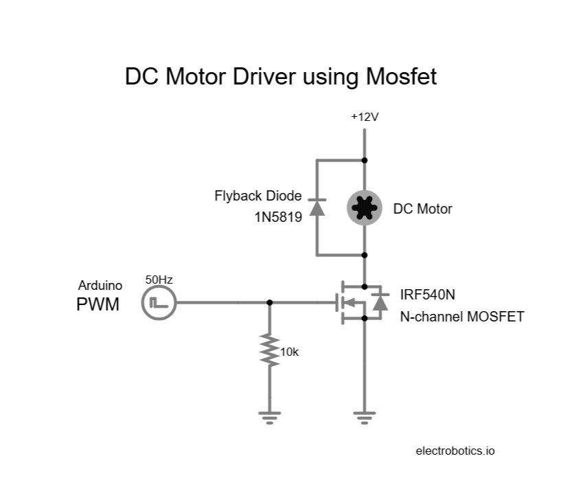
Motor drivers are essential for controlling DC motors with microcontrollers like Arduino and ESP32, as microcontrollers cannot supply sufficient current to drive motors directly. In this project, we build a MOSFET-based motor driver, which efficiently controls motor speed and direction using Pulse Width Modulation (PWM). MOSFETs (Metal Oxide Semiconductor Field Effect Transistors) are ideal for this application due to their high efficiency, fast switching, and high current handling capabilities.
This project demonstrates how to design a basic, cost-effective motor driver circuit using N-channel MOSFETs and control it with an Arduino. It covers complete circuit details, component explanation, Arduino code for PWM speed control, and the final assembly steps.

Components Required
- Arduino or ESP32 (or compatible controller)
- N-channel MOSFET (e.g., IRF640N, IRF540N or IRLZ44N)
- Flyback Diode (e.g., 1N5819 or 1N5408)
- DC Motor (6V, 12V, or 24V )
- 10kΩ Resistor (for gate pull-down)
- External Power Supply (9V, 12V, or 24V depending on motor)
- Breadboard and Jumper Wires
- Optional: Heat Sink for MOSFET (if driving high current)
Detailed Description of Components
1. MOSFET (IRF540N)
A Mosfet is a power transistor that acts as an electronic switch. It is used to handles large currents and allows fast switching. In this project, it enables PWM speed control of the motor without heating excessively.
Key Features:
- High current capability (over 20A)
- Low On-Resistance
- Fast switching speed
- Logic level gate control (depending on model)
2. Flyback Diode (1N5819)
When motors stop or change speed, they generate a reverse voltage (back EMF) or voltage spike that can damage the MOSFET. The Flyback diode safely dissipates this voltage by providing a path for the reverse current.
3. DC Motor
A simple brushed DC motor that will be controlled using the PWM signals generated from the Arduino.
4. Resistors (10kΩ)
These are connected between the gate and ground of the MOSFET to ensure the MOSFET stays OFF when the Arduino pin is not driving it (avoiding floating and false triggering).
5. Arduino or ESP32
A microcontroller board that generates the PWM signals for driving mosfet. It controls the speed of motor by varying the duty cycle of the PWM from arduino or esp32.
Applications
- Robotics: To control wheels, robotic arms, or conveyor belts.
- Automotive: Electric window control, seat adjustment mechanisms.
- Industrial Control: Conveyor belts and automated manufacturing equipment.
- Home Automation: Motorized curtains, smart fans, or garage doors.
- DIY Projects: RC cars, boats, and moving mechanical parts.
- Electric Vehicles: Controlling traction motors.
- Fans and Pumps: Adjusting airflow and fluid flow.
- Home Automation: Motorized curtains, doors, and blinds.
Advantages of MOSFET Motor Driver
- Advantages of MOSFET Motor Driver
- High Efficiency: Very low heat generation during operation.
- Fast Switching: Ideal for high-speed PWM control.
- High Current Handling: Suitable for medium to heavy motors.
- Simple and Cheap: Only a few components needed compared to motor driver ICs.
Conclusion
Creating a MOSFET-based motor driver is a fundamental yet crucial project for anyone diving into motor control with microcontrollers like Arduino. This design provides a practical, efficient, and flexible solution to control DC motors with PWM. By understanding the role of each component and following the simple circuit connection, you can easily implement speed control for various types of projects.
Moreover, learning how to interface power electronics with control electronics (Arduino + MOSFET) is an essential skill that opens doors to advanced projects like electric vehicles, smart home devices, and robotic systems.